Ray Tracing
Ray Tracing reuses the compute-output flow from Compute Shader, but each thread now traces a camera ray through an acceleration structure. The scene contains a triangle floor and three procedural spheres represented by axis-aligned bounding boxes.
This guide explains the Zenith.NET acceleration structures, resource handles, inline ray-query interface, output texture, and synchronization. The complete shader also implements soft shadows, rough reflections, checkerboard filtering, and tone mapping; those supporting effects are summarized rather than derived line by line.
Result
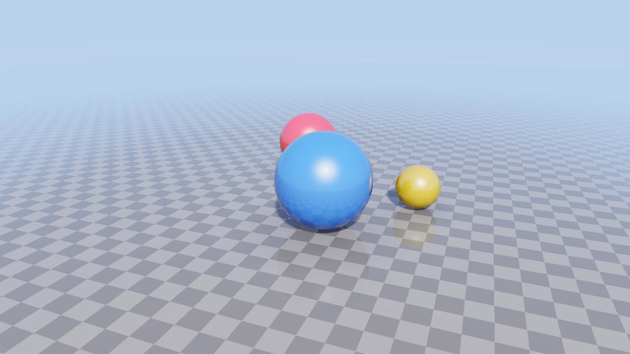
The camera orbits a checkerboard floor and three colored spheres. Primary rays determine the visible surface, while additional queries produce shadows and reflections.
Important
Inline ray tracing is optional. Check App.Context.Capabilities.RayTracingSupported before creating any acceleration-structure resources.
Frame overview
Acceleration structures are built once during renderer construction. Every frame updates the camera, regenerates the output texture, and presents it:
flowchart LR
    A[Update camera constants] --> B[Output to Storage]
    B --> C[Bind ray-query compute pipeline]
    C --> D[Dispatch one thread per pixel]
    D --> E[Output to Sampled]
    E --> F[Present texture]
The output is recreated after a framebuffer resize, but the scene geometry and acceleration structures remain valid.
Scene structure
The acceleration structures form a two-level hierarchy:
flowchart TD
    A[TLAS] --> B[Floor instance]
    A --> C[Sphere instance]
    B --> D[Triangle BLAS]
    C --> E[AABB BLAS]
    D --> F[Floor vertex and index buffers]
    E --> G[AABB buffer]
    H[Sphere structured buffer] --> I[Inline sphere-intersection logic in CSMain]
- A bottom-level acceleration structure, or BLAS, describes geometry.
- A top-level acceleration structure, or TLAS, instances one or more BLAS objects into the traced scene.
- Triangle geometry can be intersected directly by traversal hardware.
- An AABB narrows traversal to a candidate region; the shader must test and commit the exact procedural intersection.
The sphere structured buffer is not part of the AABB geometry description. The shader reads it separately to recover each candidate's center, radius, and color.
Resource map
| Resource | Usage | Role |
|---|---|---|
| Floor vertex buffer | StorageReadOnly |
Triangle BLAS positions |
| Floor index buffer | StorageReadOnly |
Triangle BLAS indices |
| AABB buffer | StorageReadOnly |
Procedural BLAS bounds |
| Sphere buffer | StorageReadOnly |
Exact intersection and material data |
| Floor BLAS | Acceleration structure | Triangle geometry |
| Sphere BLAS | Acceleration structure | Procedural AABB geometry |
| TLAS | Acceleration structure | Scene instances supplied to ray queries |
| Constant buffer | Constant |
Camera and three resource handles |
| Output texture | Storage and Sampled |
Compute output and presenter input |
| Compute pipeline | CSMain |
Primary and secondary inline queries |
Build-input buffers must remain alive until the BLAS build or update submission completes. The BLAS objects themselves must remain alive for as long as a TLAS that instances them is in use. The sphere buffer has an additional lifetime requirement because the shader reads it during every frame.
Check device support
Fail before allocating workload resources when the selected device does not expose ray tracing:
if (!App.Context.Capabilities.RayTracingSupported)
{
    throw new PlatformNotSupportedException("Ray Tracing is not supported by the selected device.");
}
Check the capability before creating the shaders and acceleration structures required by this workload.
Create scene geometry
The floor uses four positions and six indices. Three Sphere values provide procedural geometry and shading data. Convert each sphere into an AABB:
Aabb[] aabbs = new Aabb[spheres.Length];
for (int index = 0; index < spheres.Length; index++)
{
    aabbs[index] = new(spheres[index].Center - new Vector3(spheres[index].Radius), spheres[index].Center + new Vector3(spheres[index].Radius));
}
Upload all four arrays:
floorVertexBuffer = App.LoadBuffer(floorVertices, BufferUsages.StorageReadOnly);
floorIndexBuffer = App.LoadBuffer(floorIndices, BufferUsages.StorageReadOnly);
aabbBuffer = App.LoadBuffer(aabbs, BufferUsages.StorageReadOnly);
sphereBuffer = App.LoadBuffer(spheres, BufferUsages.StorageReadOnly);
constantBuffer = App.LoadBuffer([new Constants()], BufferUsages.Constant);
These buffers are read during acceleration-structure construction or shader execution. They are not vertex and index bindings in a graphics render pass.
Create the compute pipeline
Load the CSMain entry point and create the compute pipeline used for every inline ray-query dispatch:
using Shader computeShader = App.LoadShader("RayTracing.slang", "CSMain");

rayTracingPipeline = App.Context.CreateComputePipeline(new() { ComputeShader = computeShader });
The acceleration structures and descriptor handles become inputs to this pipeline; no separate ray-tracing pipeline or intersection-shader stage is created.
Build the bottom-level structures
Record acceleration-structure construction on a compute command buffer:
CommandBuffer commandBuffer = App.Context.ComputeQueue.CommandBuffer();
The sample submits this one-time build and waits for it to complete before rendering begins.
Describe the indexed triangle geometry for the floor:
floorBlas = commandBuffer.BuildAccelerationStructure(new BottomLevelAccelerationStructureDesc()
{
    Geometries =
    [
        RayTracingGeometry.Triangles(new()
        {
            VertexBuffer = floorVertexBuffer,
            VertexFormat = PixelFormat.R32G32B32Float,
            VertexCount = (uint)floorVertices.Length,
            VertexStrideInBytes = (uint)sizeof(Vector3),
            IndexBuffer = floorIndexBuffer,
            IndexFormat = IndexFormat.UInt32,
            IndexCount = (uint)floorIndices.Length,
            Transform = Matrix4x4.Identity
        }, true)
    ],
    BuildFlags = AccelerationStructureBuildFlags.PreferFastTrace
});
The vertex format and stride tell the builder how to read each Vector3. The final true marks the geometry opaque, allowing traversal to accept triangle hits without an any-hit stage.
The procedural BLAS instead reads an array of AABBs:
sphereBlas = commandBuffer.BuildAccelerationStructure(new BottomLevelAccelerationStructureDesc()
{
    Geometries =
    [
        RayTracingGeometry.Aabbs(new()
        {
            Buffer = aabbBuffer,
            Count = (uint)spheres.Length,
            StrideInBytes = aabbBuffer.Desc.StrideInBytes
        }, true)
    ],
    BuildFlags = AccelerationStructureBuildFlags.PreferFastTrace
});
The AABBs accelerate traversal, but they do not turn boxes into visible surfaces. CSMain later performs the exact sphere intersection for each procedural candidate.
Build the top-level scene
Create one identity-transform instance for each BLAS:
tlas = commandBuffer.BuildAccelerationStructure(new TopLevelAccelerationStructureDesc()
{
    Instances =
    [
        new()
        {
            AccelerationStructure = floorBlas,
            InstanceId = 0,
            VisibilityMask = 0xFF,
            Transform = Matrix4x4.Identity
        },
        new()
        {
            AccelerationStructure = sphereBlas,
            InstanceId = 1,
            VisibilityMask = 0xFF,
            Transform = Matrix4x4.Identity
        }
    ],
    BuildFlags = AccelerationStructureBuildFlags.PreferFastTrace
});

commandBuffer.Submit().Wait();
The CPU wait ensures both BLAS objects and the TLAS are complete before construction returns. The instance IDs distinguish scene entries; procedural primitive indices still identify individual AABBs inside the sphere BLAS.
Data contract
Shared C#/Slang layout requires care around three-component vectors. The CPU sphere packs center and radius into the first 16 bytes, followed by color at byte 16:
[StructLayout(LayoutKind.Explicit, Size = 32)]
file struct Sphere
{
    [FieldOffset(0)]
    public Vector3 Center;

    [FieldOffset(12)]
    public float Radius;

    [FieldOffset(16)]
    public Vector3 Color;
}
Slang uses two float4 backing fields and exposes semantic properties:
struct Sphere
{
    private float4 CenterAndRadius;

    private float4 ColorAndPadding;

    property float3 Center
    {
        get {
            return CenterAndRadius.xyz;
        }
    }

    property float Radius
    {
        get {
            return CenterAndRadius.w;
        }
    }

    property float3 Color
    {
        get {
            return ColorAndPadding.xyz;
        }
    }
};
This explicit storage keeps the structured-buffer stride at 32 bytes across the supported graphics APIs.
The frame constants use the same technique for camera position, followed by three handles:
| Offset | C# | Slang |
|---|---|---|
| 0 | Vector3 Position |
PositionAndPadding.xyz |
| 16 | tlas.Handle |
RaytracingAccelerationStructure Scene |
| 24 | sphereBuffer.StorageReadOnlyHandle |
StructuredBuffer<Sphere> Spheres |
| 32 | outputTexture.StorageHandle |
RWTexture2D<float4> OutputTexture |
Inline ray-query interface
Each compute thread reconstructs one camera ray and begins traversal through the TLAS:
RayDesc ray;
ray.Origin = cameraPos;
ray.Direction = rayDir;
ray.TMin = RayEpsilon;
ray.TMax = 1000.0;

float3 sphereHitNormal = float3(0.0);
float3 sphereHitColor = float3(0.0);

RayQuery<RAY_FLAG_NONE> query;
query.TraceRayInline(constants.Scene, RAY_FLAG_NONE, 0xFF, ray);
The two temporary values preserve the normal and material color produced by a procedural sphere candidate after that candidate is committed.
Triangle intersections can become committed hits automatically. Procedural AABBs are reported as candidates and require an exact test:
while (query.Proceed())
{
    if (query.CandidateType() == CANDIDATE_PROCEDURAL_PRIMITIVE)
    {
        uint sphereIndex = query.CandidatePrimitiveIndex();
        Sphere sphere = constants.Spheres[sphereIndex];

        float3 ro = query.CandidateObjectRayOrigin();
        float3 rd = query.CandidateObjectRayDirection();

        float t = IntersectSphere(ro, rd, sphere);

        if (t >= query.RayTMin() && t <= query.CommittedRayT())
        {
            float3 hitPoint = ro + rd * t;

            sphereHitNormal = normalize(hitPoint - sphere.Center);
            sphereHitColor = sphere.Color;

            query.CommitProceduralPrimitiveHit(t);
        }
    }
}
CandidatePrimitiveIndex maps the AABB candidate back to its sphere record. The shader computes a positive intersection distance and commits it only when it lies inside the query's valid interval.
After traversal, committed status selects the visible surface:
if (query.CommittedStatus() == COMMITTED_TRIANGLE_HIT)
{
    float3 hitPoint = ray.Origin + ray.Direction * query.CommittedRayT();
    color = ShadeFloor(hitPoint, rayDir, cameraPos);
}
else if (query.CommittedStatus() == COMMITTED_PROCEDURAL_PRIMITIVE_HIT)
{
    float3 hitPoint = ray.Origin + ray.Direction * query.CommittedRayT();
    color = ShadePrimarySphere(hitPoint, rayDir, cameraPos, sphereHitNormal, sphereHitColor);
}
else
{
    color = SampleSky(rayDir);
}
Supporting shading flow
The remaining shader functions improve the sample image but do not change the Zenith.NET resource interface:
flowchart TD
    A[CSMain primary query] --> B[Shade floor]
    A --> C[Shade sphere]
    A --> D[Sample sky]
    B --> E[Shadow queries]
    B --> F[Reflection query]
    C --> E
    C --> G[Rough reflection queries]
    B --> H[ACES tone mapping]
    C --> H
    D --> H
Shadow rays reuse the TLAS with RAY_FLAG_ACCEPT_FIRST_HIT_AND_END_SEARCH. Reflection rays use the same procedural-candidate loop as the primary query. Multiple jittered directions soften shadows and reflections. Finally, ACESFilm maps the accumulated HDR color into the output range.
You can replace these helpers with simpler colors while preserving the acceleration structures, descriptors, pipeline, dispatch, and texture transitions described by this guide.
Create and update the output
Create an R32G32B32A32Float texture with Sampled | Storage usage when the renderer first sees a valid framebuffer size. A new texture is initially established as sampled because every subsequent frame follows the same repeating cycle:
Sampled -> Storage -> compute writes -> Sampled -> presenter reads
Update the camera and resource handles before dispatch:
Constants constants = new()
{
    Position = new(12.0f * MathF.Sin(totalTime * 0.3f), 4.0f + MathF.Sin(totalTime * 0.2f), -12.0f * MathF.Cos(totalTime * 0.3f)),
    Scene = tlas.Handle,
    Spheres = sphereBuffer.StorageReadOnlyHandle,
    OutputTexture = outputTexture.StorageHandle
};
Then record the state changes and dispatch:
commandBuffer.Transition(outputTexture, default, TextureLayout.Sampled, TextureLayout.Storage);

commandBuffer.SetPipeline(rayTracingPipeline);
commandBuffer.SetConstantBuffer(constantBuffer, 0);
commandBuffer.Dispatch((App.Width + ThreadGroupSize - 1) / ThreadGroupSize, (App.Height + ThreadGroupSize - 1) / ThreadGroupSize, 1);

commandBuffer.Transition(outputTexture, default, TextureLayout.Storage, TextureLayout.Sampled);

App.PresentTexture(commandBuffer, drawable, outputTexture, true);
Unlike the static grayscale image, this workload dispatches every frame because the camera moves. Passing true to the presenter fits the output to the framebuffer.
Resize and lifetime
Resize disposes only the framebuffer-sized output texture. The next frame recreates it and uploads its new storage handle.
Dispose resources from users to dependencies:
outputTexture?.Dispose();

rayTracingPipeline.Dispose();
constantBuffer.Dispose();
tlas.Dispose();
sphereBlas.Dispose();
floorBlas.Dispose();
sphereBuffer.Dispose();
aabbBuffer.Dispose();
floorIndexBuffer.Dispose();
floorVertexBuffer.Dispose();
The TLAS is released before the BLAS objects it instances. The sphere buffer remains live because ray-query shading reads it every frame.
Inspect the result
Run the host and select Ray Tracing on a supported device. Confirm that:
- the floor, three spheres, sky, shadows, and reflections are visible;
- the camera orbits continuously;
- resize recreates an output that fills the new framebuffer;
- validation reports no acceleration-structure lifetime, descriptor, or texture-layout errors.
A sky-only image often indicates a missing TLAS handle or visibility-mask mismatch. Box-shaped procedural hits indicate that AABBs are being treated as bounds without committing the exact sphere intersection. A stale or blank image usually points to the output handle or Sampled/Storage transition sequence.
Explore further
- Return a constant color for each committed status to inspect traversal without the supporting shading functions.
- Set
ShadowSamplesandReflectionSamplesto1and compare cost and image quality. - Disable reflections while leaving primary and shadow queries unchanged.
- Move one TLAS instance with its transform instead of changing the source geometry.
- Change a sphere radius and update both its structured-buffer record and AABB.
Complete source
Continue with Mesh Shading to explore another optional workload that replaces fixed vertex and index fetch with programmable geometry emission.